PLIS = Pressurized Liquid Injection System
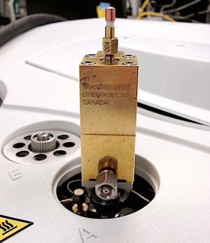 The PLIS valve assembly is intended for the introduction of pressurized liquid samples into On-Line, At-Line or laboratory based Agilent/Perkin Elmer Gas Chromatographs equipped with Split/Splitless capillary inlets. It has a reciprocating "STEM" with a machined groove at its lower extremity designed to contain the pressurized liquid sample to be analyzed. The "STEM" is moved from the load position (upper) to the inject position (lower) by a pneumatic piston that is electro/pneumatically controlled by the Agilent/Perkin Elmer GC keyboard or control software. In the load position, the "STEM" grove is positioned in the center of the sample chamber through which flows the pressurized fluid. In the inject position, the "STEM" grove is positioned in the sample transfer zone just below the lower seal.
When the PLIS is activated and the "STEM" traverses the lower seal with the pressurized sample into the sample transfer zone, the sample flashes from the grove and is carried by the carrier gas into the GC capillary inlet system. Heat for the flash vaporization is supplied by the capillary inlet system that is operating at an elevated temperature compatible with the matrix to be analyzed.
Because the flash vaporization is augmented by an external heat source that is close coupled to the PLIS, a broad boiling range of hydrocarbons (C1 to C20) within the matrix can be successfully analyzed. The extreme high end of this hydrocarbon range must be at low concentrations due to the nature of the physical properties of the respective components.
Once the sample has been successfully transferred to the capillary inlet system, normal capillary principles of gas chromatography are in control of the remaining analytical process.
The PLIS valve was specifically designed for the above-described process however is not unique in its concept. It is however very unique in its level of performance, adaptability to bench top gas chromatographs, heat ability and is easily differentiated from similar products in that it:
- Can introduce pressurized liquid samples with very broad boiling range components: C2 to C20
- Can be field upgraded to a heated stem version for beyond C20 analysis; (up to C40+ w/HPLIS)
- Is pressure rated to handle the most demanding pressurized liquid sample; ethane (C2; 1200 psi)
- Has close coupling to the heated inlet (no cold transfer lines)
- Has a variety of STEMs (groove volumes) that can be field changed to match the application requirements
- Can be removed for conversion to syringe injection
- Can inject rapidly or slowly without any change in GC performance
- Is compact and simplistic in design and operation
- Features "no flow interruption" during injection
- Has an integrated pneumatic actuator
- Has easy access for field service.
Specifications:
- Sample Pressure Rating: 1200 psig @ 30 C using Helium as the test media
- Static Pressure loss of Helium over 1 hour; < 100psi
- Sample volumes available: 0.25, 0.5, 0.75, 1.0, 1.5 and 2.0 uL
- Sample Chamber Material: 316 Stainless Steel terminating in 1/8" tubes
- Sample Chamber cooling: temperature reduction by 20 C when room temp air under 2 psi, pressure is applied to lower brass block fitting and Injection port temp is at 400C; Vortex" cooled air can further reduce this critical zone temperature.
- Air Pressure Actuation: > 75 psig; dry air Maximum Air Pressure recommended: 125 psig;
- O-ring Material: Nitrile rubber
- Pneumatic Piston Lubricant: Dimethyl Siloxane (Silicone) Grease.
- Sample Chamber Seal material: Virgin Teflon.
- Pneumatic Body material: Brass.
- Sample/Carrier path material: 316 Stainless Steel; optionally available in Hastelloy "C" at optional cost.
- Injection Speed: Typical < 350 ms with > 90 psi dry air, chromatographic performance is independent of speed.
- Internal Dead Volume in Sample Transfer Zone: approximately 80 uL in inject position.
PLIS Operation
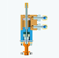
The operation of PLIS is based on a specific sample volume that is moved through seals from the sample stream (load position) to the inject position. This movement is controlled by a timed event resident in the gc time table.
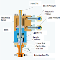
PLIS has a Stem that is attached to a pneumatic piston and this Stem runs from the top of PLIS through the PLIS body and exits on the bottom side of the lower seal just above the injection port. When 90 psi air pressure is applied to the bottom side of the pneumatic piston, the piston moves up and moves the Stem groove to the load position. In the load position, the Stem groove is positioned in the sample stream and right in the middle of the sample chamber. Sample comes in on one side of the sample chamber and exits the opposite side. When fresh sample has purged the sample chamber of the previous sample, the flow is stopped with a plug valve on the outlet side of the sample chamber.
The sample in the sample chamber is pressurized up to the sample cylinder pressure so as to ensure the sample is in single liquid phase. At this point, the gc Start button is pressed which activates a solenoid and applies 90 psi air pressure to the top side of the pneumatic piston. This drives the piston down and moves the sample/Stem in the Stem groove into the vapourizer adapter which is secured to the gc injection port with the big black nut. Carrier gas enters PLIS at the small lower 1/16" brass union and flushes the vapourized sample from the Stem groove into the injection port liner and then into the column.
The vapourizer adapter derives its heat from the injection port it is attached to. In the case of HPLIS the Stem groove volume is heated to approximately 450C for about 1.25 seconds. The Stem is left in the inject position for 20 seconds and then automatically retracted into the load position.
After the analysis is complete, the cycle can be repeated. This makes PLIS very adaptable to On-Line applications.
Click here for more information.